Please complete this form and we will contact you quickly.
H.T. Automatic Voltage Stabilizers are used to get stabilized H.T. input voltage, irrespective of the voltage variations received from electricity supply authorities. Additionally, these stabilizers also prevent the transformer and other electrical equipment from getting overloaded. Wide voltage variation ranges are taken care continuously and in on load condition. The variations of more than ± 1% of the rated output voltage are sensed through solid state relay. This relay operates on 230 V, 110Ø supply and sends signals to the stabilizer’s motor, which drives the roller mechanism in lower and higher direction to bring voltage to the rated output voltage within +- 1%. The Accuracy of +-1% may vary depending on the specific requirement of customer.
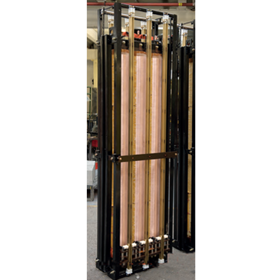
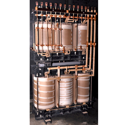
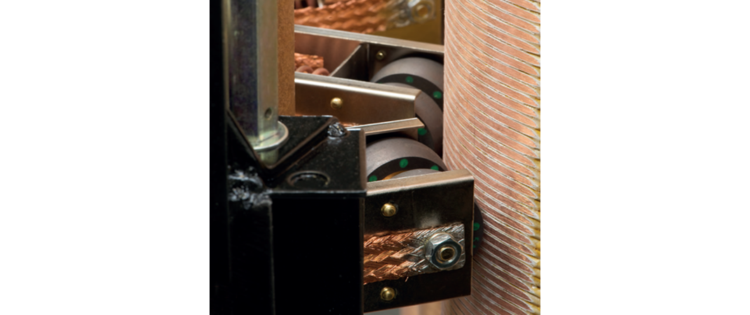
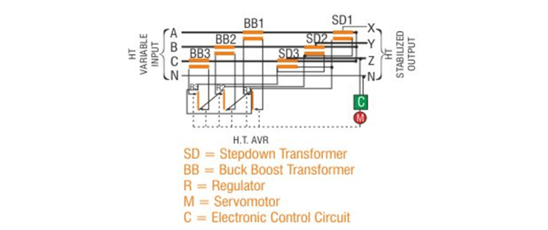 H.T. Automatic Servo Voltage Stabilizers have helical coils mounted on a conventional laminated core. Carbon rollers are assembled on a fibre glass carrier board and are traverse to the length of the coil track. The rollers are connected to the electric output terminals. Nearby the regulating coil, a number of compensating winding is connected in parallel, which are short circuited to reduce the effect of core-flux fringing. It also keeps the reactance of the regulator constant at any position of the rolling contact.
These HT-Automatic Voltage Regulators are widely used in different industrial sectors for getting a stable input voltage.
| CONSTRUCTION |
|---|
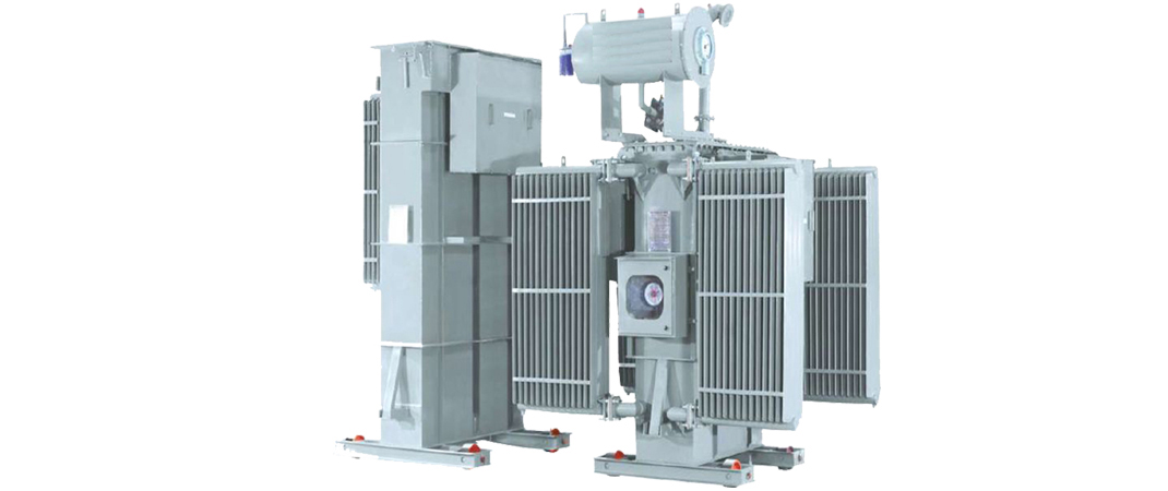
| Generally H. T. Automatic Voltage Regulator consist of two tanks to facilitate servicing of the moving parts of Rolling Contacts and other components in the regulator without disturbing the main tank containing Transformers . |
| Carbon rollers goes around the length of the coil track & are assembled on a fiber glass carrier board |
| The rollers are connected to the electric output terminals |
| Parallel connection of compensating winding near the regulating coil is done |
| The connection between the windings and regulating coils is short circuited so as to reduce the effect of core-flux fringing |
| It keeps the reactance of the regulator constant at any position of the rolling contact |
| STANDARD SPECIFICATION |
|---|
| Capacity :Up to 15000 KVA |
| No. of Phases :3 Phase |
| Frequency: 50 Hz. |
| Voltage Class :11,22,33 KV |
| Voltage Range :+ 20% to - 30% (or any voltage range as per site client requirements) |
| Technology: Stepless linear regulator type (Vertical rolling contact type) |
| Insulation :Class ‘A’ |
| Vector Group :Dyn 11 |
| Duty Cycle :Continuous |
| Winding :Electrolytic Grade Copper Wound |
| Terminals :As per required |
| STANDARD FITTINGS |
|---|
| Rating & Diagram plate :Earthing terminals |
| Lifting lugs :Thermometer pocket |
| Oil Conservator with drain plug :Air release hole with plug |
| Oil Level indicator :Explosion vent with diaphragm |
| Top-filter Valve: Inspection cover. |
| Silica gel breather :Drain –cum-bottom-filter valve |
| Cooling radiators :Uni / Bi- directional rollers |
| ADVANTAGES |
|---|
| Utilization of the Distribution Transformer is to its full capacity as the H.T. AVR shares the load of the Transformer and the connected load. |
| Losses are less as the incoming voltage either low or high is corrected at the initial stage only. |
| Fluctuations in the H.T. Supply are not passed on to the Distribution Transformer. |
| Installation Cost is less in comparison to L.T. Automatic Servo Voltage Stabilizer, for higher ratings. |
| Single Unit of H.T. Automatic Servo Voltage Stabilizer can be connected to more than one Distribution Transformer. |
| Economical for huge capacities like 2500 KVA and above or for wide voltage fluctuation range (eg. 8 KV – 13 KV, 28 KV – 36 KV etc.) |
| Can be placed anywhere on the feeder line. |
| Motor fitting is external, so any change of the motor or motor shaft can be easily done without opening the top cover. |
| Output Voltage of H.T. AVR remains constant at any connected Load and up to full load. |
| Response time for Voltage correction is 20 micro seconds. |
| Low replacement cost |
| 5% to 10% saving on energy consumption |
| Reduction in breakdown period of the machines |
| 100% capacity |
| On Load step-less voltage variation |
| TECHNICAL ADVANTAGES |
|---|
| Very Easy to maintain – No Specialize Manpower is required. |
| Undistorted output characteristics ie. No wave from distortion. |
| Moving parts on L.T. side and its mass is extremely low, only few lb-inch torque. |
| Energy savings. |
| High efficiency (about 99%) and minimum no load losses. |
| Simplicity and flexibility of design |
| On load stepless voltage variation |
| Long service life |
| Impulse tested |
| Regulating coils are wound with rectangular conductors on their edge, thus giving high mechanical strength compared to other designs. |
| Low replacement cost. |
© Mehta power - 2020 | All Right Reserved. Designed By We Choice